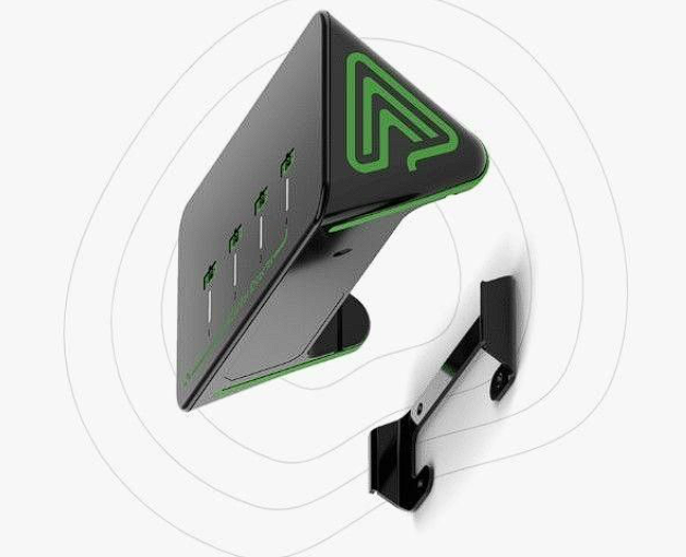
DryContactDirector Module
About the product
DryContactDirector is an advanced automation and data management solution that allows you to seamlessly operate up to 64,000 dry contacts without any need for manual input. DryContactDirector can automate your devices and uninterrupted functionality. With its advanced capabilities, become possible to streamline operations, improve productivity, and ultimately achieve greater success in growing business. A dry contact is a volt-free passive contact having no energy applied to its contacts internally. From the user perspective the dry contact simply operates like an ordinary switch that opens or closes the circuit. The DryContactDirector Module uses internal relays operating as fully isolated switches allowing the user to connect them to various independent circuits. The DryContactDirector Module is a Wi-Fi wireless load management device. It switches loads on and off according to system configuration.
Functional
-
Controlling up to 64,000 electrical Devices in one system by adding extra Modules.
-
Can manage up to 48 rules for all devices.
-
Single Module can handle 4 dry contacts.
-
Automating and controlling multiple high-power or low-voltage equipment with one controller.
-
It supports a wide input voltage range of up to 230V and a wide input current range of up to 10A.
-
Customizable Alerts: Set notifications for critical parameter changes, ensuring prompt action when needed to maintain ideal growing conditions.
Delivery set
-
A module;
-
Metal holder;
-
Connector 0,75 A (needs power adapter).
Installation
! WARNING !During installation, operation, testing and inspection, adherence to all the handling and safety instructions is mandatory. When used in 120Vac/60Hz or 230Vac/50Hz (Hazardous Live) circuits, the installation must be performed by authorized and certified electricians. Failure to do so may result in injury or loss of life and damage to the equipment.
● This product must be operated under the specified operating specifications, as described in the latest technical specification datasheet.
● Configure the product so that the load connected is not switched on or off more frequently than specified by the load manufacturer.
● Do not use the product if it is damaged or malfunctioning.
● Do not let the product come into contact with water or other liquids.
● This product contains no user-serviceable parts. Do not attempt to open, modify, disassemble or repair any component of the device.
● The enclosed documentation is an integral part of this product. Keep the documentation in a convenient place for future reference and observe all instructions contained therein.
Ambient Operating Conditions
Environment | Indoor use |
Temperature | 0-50 C or 32-122 F |
Max. rel. humidity | 90%, non-condensing |
Permissible installation attitude | 5000 m above sea level |
Process of installation
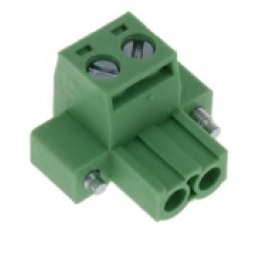
- Use the provided terminal block plug to connect the DryContact to the controlled load:
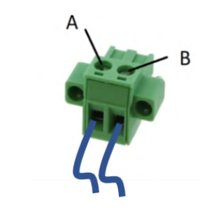
- Use the wire fixing screws (A and B) to affix the load wires (AWG 12-26, 0.13-3.31mm2, according to current capacity required by applicable standard and application needs):
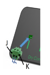
- Insert the terminal block plug into the DryContactDirector terminal socket and tighten it using screws J and K:
- Caution!
When the DryContactDirector is used to control equipment powered by 120Vac/60Hz or 230Vac/50Hz circuits, it must be installed in standard electrical enclosure (electrical cabinet or box) to prevent access to hazardous live exposed parts of the terminal block!
- Caution!
Due to the fact the DryContactDirector has no internal fuse protection, when it is used in 120Vac/60Hz or 230Vac/50Hz circuits, an external 1-Pole circuit breaker rated 10A and certified in accordance with IEC 60947-2 (in US/Canada a Listed branch circuit protective circuit breaker) shall be used for overcurrent protection and mains disconnection.
Use cases
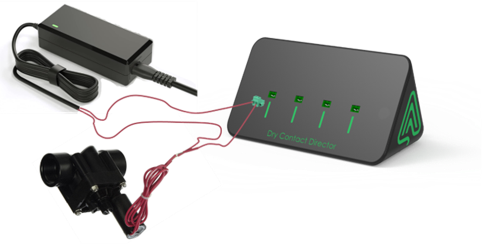
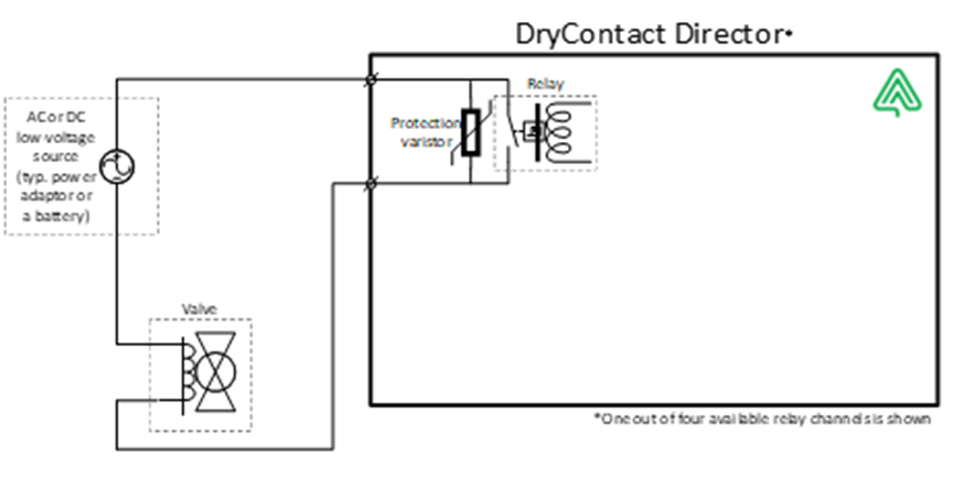
Example use of DryContact Director device in low-voltage low-power applications such as irrigation solenoids, pumps, sprinkler valves and similar equipment powered typically by 5/9/12/24Vdc or 12/24Vac (please refer to DryContact Director specifications for rated voltage and current values) | |
| |
Description of the electrical connection of the above illustrated use case, where the dry contact connector has no dedicated polarity and can be as a mechanical switch in series to power supply connected to any wire of the AC or DC power adaptor. | |
| |
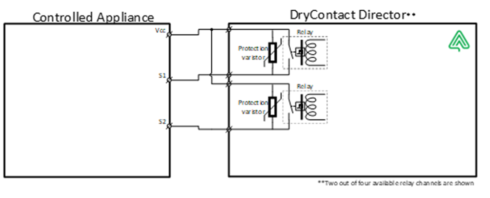
DryContact Director can be used to control various appliances having a dedicated low-voltage control input signal, such as hydraulic and solenoid controlled valves, heat pumps, centrifugal fans and blowers, cross-flow fans, etc. Such equipment usually provides a control DC voltage source (Vcc = 5V, 9V or 12V) next to the ON/OFF signal input to enable installation of simple jumper between the two in case of continuous uncontrolled operation need or a simple switch or smart dry contact connection for controlled operation. In some cases there are more than one input signal (for example to control several settings of fan speed) as shown in Figure 3 illustrating two such inputs – S1 and S2. | |
| |
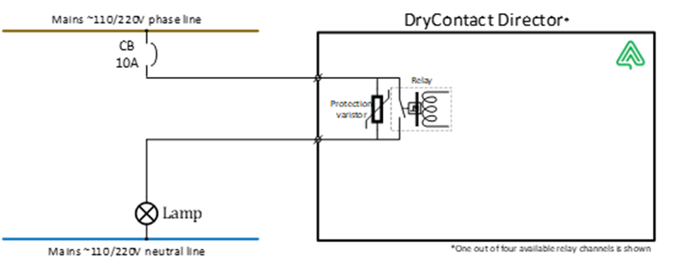
The relays inside the DryContact Director are powerful enough to switch not only low-voltage circuits but also lite loads connected to the mains electricity (please refer to DryContact Director specifications for rated voltage and current values). The use case in Figure 4 illustrates a simple lighting circuit control, which represents “lite” load with regards to relay characteristics. Working with resistive loads connected to the relay output, the entire rated range of voltage and current can be used without any limitations. | |
| |
A special attention must be given to the current protection scheme due to the fact the relay’s poles are directly attached to the connector without internal fuse. Since in the majority of the cases greenhouses equipment is centrally powered at the electrical cabinet, the physical location of the DryContact Director will be within such cabinet and it must utilize an external dedicated 10A circuit breaker for overcurrent protection. A resistive load is defined as a device with its inrush and switch-off currents equal to the steady-state values. That is, a load whose electrical resistance is always the same and does not change in time; therefore, the current is also constant from the switch-on moment to the switch-off moment. Devices that mostly behave as resistive loads include:
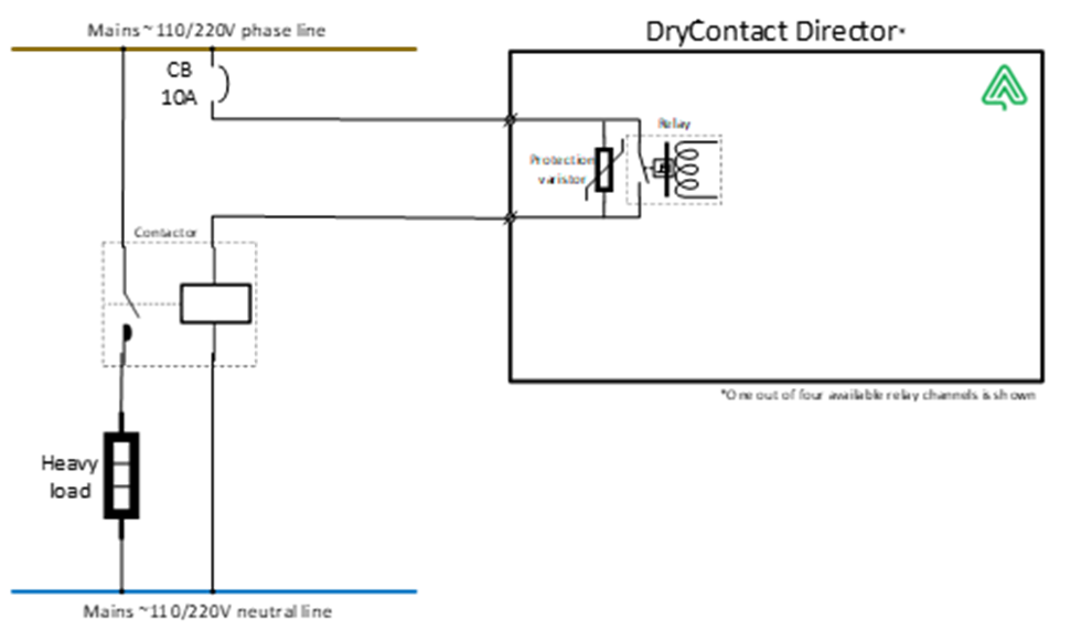
The biggest “enemy” of relays is an inductive load. Its behavior is the most damaging, capable of destroying (welding or burning) the relay contacts. The problems come when the relay contacts open, and the inductive load is disconnected. Due to the underlying physics principle, the inductive load tends to maintain the same current that was flowing through it before the disconnection. To this end, a voltage of the magnitude and polarity necessary to maintain this current is temporarily induced at the terminals of the inductive load. This voltage spike is influenced by the inductance (the higher the inductance, the higher the voltage spike) as well as the switch-off time and method. Although DryContact Director relays are protected by internal varistors with energy absorbing capability of up to 75 Joules and peak pulse currents of up to 4500 Amperes, it is highly recommended to use contactors when operating devices that behave as inductive loads. The examples of such loads are:
To better understand this use case, the difference between relays and contactors must be emphasized. Similar to relays, contactors are electrically controlled switching devices, designed for repeatedly opening and closing a circuit. Contactors are principally designed for use in applications where a large amount of current needs to be switched. For that purpose, contactors typically offer a much wider range of safety cut-offs and protections, reflecting the fact that they are designed for higher power applications. Next figure illustrates the use of controlling such high-power circuits in general and heavy inductive loads in particular using DryContact Director controlling the contactors switching these loads on and off.
| |
| |
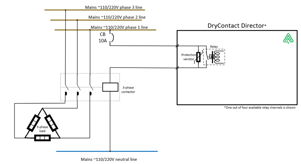
The contactors are always located inside the electrical cabinet and like in the previous case, the controlling DryContact Director will be mounted within same cabinet and utilize an external dedicated 10A circuit breaker for overcurrent protection. In a similar manner the 3-phase load can be controlled using external 3-phase contactor. | |
| |